Featured post

Pentewan Light Railway

The Pentewan Railway in Cornwall was possibly unique in having three* gauges in its lifetime. Christopher Hawkins built the original rai...

Wednesday, 6 January 2021

PLR Ready for transit

It took several days to separate all the boards and get them downstairs and then dismantle and clear all the staging and workbench etc. Here are some photos of the progress.

All the boards downstairs into the conservatory:


Notice the odd shapes and height of some of the boards - this is certainly not a railway built on a flat piece of board!

Crated up ready for transit:


There are 4 crates each with several boards within made using the wood from the loft staging and with the high hill as a separate piece. The crates are designed to be carried by two people and stack for transit. I've used pallet cling wrap on the scenic boards to keep them clean as they could be stored for some months before the new log cabin home is built. The removal people frowned when they saw it all (they had been warned).

The clear loft:


What a nice railway room it would make! However, I don't think the new owners are that minded. This room was actually one of the reasons we (well me) wanted to buy the house all those years ago. It didn't have the floor boards nor insulation then. Note the water tank that dictated the big hill and the track spiral which tunnelled down behind it.

So Devon next!

Saturday, 28 November 2020

PLR on the move

So the time has come to consider how to get the PLR out of the loft and crated up ready for the move to Devon. Here are some pics of it in the loft before dismantling it and getting the boards downstairs for packing - and the rest of 30 years worth of accumulated rubbish treasures. My plan is to assemble the boards with added wooden framing to make 3 or 4 crates.


Friday, 11 January 2019

K1 rechip

After a lot of deliberation I have taken the plunge to replace the CT Elektronik decoders on my K1 with a Zimo MX645 for the front LP engine and a MX633 for the rear HP engine.

Although it is a heavy engine with common pickup on all 8 wheels it still suffered a little from power dropouts which mainly manifested itself in spluttery sound. Therefore the rebuild includes adding stayalives in the form of a bank of 4 x 220uf tantalum capacitors per engine.

I stripped out the memory wire rigging that operated the valve gear (forward/reverse) as it never really worked satisfactorily. However I still have a hankering to make this work so have acquired two of these tiny servos:
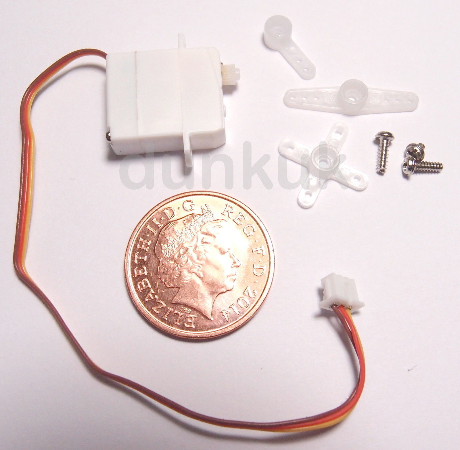
Specification:
Weight: 1.7g
Speed: 0.07sec 60deg @ 2.8v / 0.05sec 60deg @4.2v
Torque: 0.05kg @ 2.8v / 0.075kg @ 4.2v
Dead Band: <4us
Dimensions: 13 x 16 x 6mm
Plug: Micro JST - 1.25 Pitch
I've worked out that these could just fit alongside the motor in the location shown in the photo below. Don't forget this is all hidden inside the tanks - the motor, decoder and wiring only just fit as it is!

However, before I try fitting it I'm going to hook it up to the decoder and work out what settings allow the servo to move with direction. One problem is only the MX645 has the 5V supply necessary to drive these servos without extra circuitry (for which I have no space) so if successful I will probably drive the rear engine servo from the front using some spare wiring connections in the steam pipe.

There is also still the hope to add automated uncoupling using tiny RC actuators for which there is even less space for, although at least the memory wire is no longer in the way.


Update 16th Jan - I've now temporarily hooked up the servo to the +5v supply on the MX645 (soldered to a capacitor as per instructions!) and activated the servo CVs with DecoderPro and it works! I've now want to work out how to make it directional. More manual gleaning and chatting to friends methinks.

Belated update August 2019 - I came to the conclusion a few months back that it was not realistic to get the servos and operating linkage in place without complete disassembly of the engine units. In practice this would be complete breakdown of everything back to component parts of: wheels, motion, axleboxes, etc., and then build them again with some operating linkage in place. As it took me 4 1/2 years to build it in the first place, and I still have lots of other locos and track etc. to build, I decided I would abandon the operation. Thus it was reassembled, and the painting touched up and re-weathered and it is now ready for operation again. 

Postscript May 2020 - Operation of the re-chipped K1 proved problematic. The Zimo chips come with immersive drive which means you control the braking with F2. Well that's the theory but the MX633 had an older firmware version so didn't seem to have the immersive drive. Furthermore, it appeared the immersive drive on the MX645 only worked in one direction. Thus the engines were dismantled once again and the chips returned to the supplier for a firmware upgrade. For various reasons I am still awaiting their return.

Friday, 28 April 2017

Now here's a trackwork challenge

As blog readers will know I like track - narrow gauge, broad gauge, chaired, flat bottom and even trams. Thus I was in seventh heaven with a holiday in Lisbon over Easter where the narrow gauge tram system with both old and new styles of trams exhibit every classic type of track formation and runs up and down unbelievable gradients - one tram had to apply it's skid brakes before descending a hill.

I modelled trams in my youth and could be tempted again one day to try and replicate the type of scenes below.


Thursday, 27 April 2017

Lynton in O14

So my first trackmaking commission is finally finished - many months late (mainly because of taking on a new full-time job) - but just in time to free up the house for the first of my three children's weddings this year.

It is an exact to scale model of Lynton station in late SR period which just fits on five 4ft boards. It was an interesting project requiring a surprising amount of research and I owe my thanks to the many experts on the Yahoo ExmoorNG and L&B Modelling groups - and not forgetting Measured and Drawn.

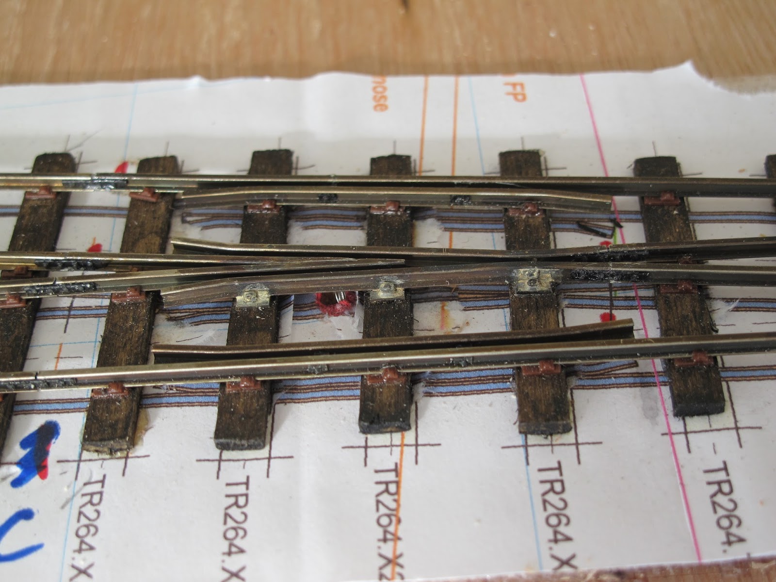
I battled with Templot to produce the plans but when it actually came to tracklaying I found these lacking and redrew much of the pointwork on plain sheets of paper.

Most of the track is SR style but with some of the sidings in original L&B style. Rail is Karlgarin code 82/7, SR baseplates are KBscale, SR sleepers are a specially cut section by Twigfolly, original sleepers are coffee stirrers, spikes are home made from staples, fishplates are from Zamzoodled. All track is laid on a thin foam base.

Some photos of the finished model below - see earlier blog posts for work in progress.

Hopefully when the whole layout is finished (he's in no hurry) I will get the chance to help the owner exhibit it.


The approach
The bay and loop turnouts (engine shed road yet to be built)

The loop and engine shed turnout

The crossover and goods shed turnout - very tricky to get right

Track fitted around the goods shed (not made by me)
The goods yard of mostly L&B style track (buildings not made by me)

SR track above - L&B below

Closeup of crossing

Closeup of switches

Thursday, 29 December 2016

Another visitor to the PLR


David John's K1 (built by Paul Berntsen) came to visit the PLR over Christmas. This is it trying out the big climb (1 in 28  with 26" radius reverse curves) with a few wagons on the back: http://youtu.be/ypnf0ot11tM

And a couple of shots of it posed with mine (I can't actually run them together as mine is DCC and David's is DC)


Sunday, 27 November 2016

More Lynton Trackmaking

After very slow progress over the summer, a burst of activity means the final three turnouts are well underway. The following photos show the sacrificial jigs I use which are made from card a copy of the template overlaid with card and straight slots cut for the rails. Flares and cosmetic rail clips (made from pins) are added later and the rails cut to length.


Wednesday, 29 June 2016

Trackmaking for Lynton

I agreed a while back to make some trackwork for a new layout of Lynton in the late SR period - all in O14 of course. We had lots of challenges with various sources and Templot to ascertain the track layout and turnout angles/dimensions which is as close to scale as we could determine. Subsequently I started a new full time and very challenging job so progress has been a lot slower than intended. Luckily the recipient has similar time challenges and is very patient.

Here are a few shots of the first turnout under test and the common crossing under construction for the next.


Tuesday, 3 May 2016

PLR Model Size and Statistics

I have often been asked the overal size of the PLR so I have included the following plan of the current configuration. This can be compared to the configuration in the 1990s and 1980s.

The key statistics are:

Overall Size: 18ft x 14ft

NG full circuit: ~ 80ft
NG mainline maximum grade: 1 in 28 (3.5%) - from lower tunnel exit to quarry loop
NG mainline minimum radius: 27in - the big spiral and a small section c. 22in between quarry and viaduct.
The quarry lines are much steeper and tighter.
SG end to end length: ~30ft
SG maximum grade: 1 in 25 (4%) - mainly in hidden track


Grid squares = 1ft 

The plan below shows the section that was exhibited at ExpoNG 2014 with the additional boards that were built to allow operation:


PLR Location and Route

The following maps show the location of the three phases of the Pentewan Railway. The PLR was the third epoc* and the approxomate area modelled is shown below.

(* The PLR of course only really existed in my model world)